
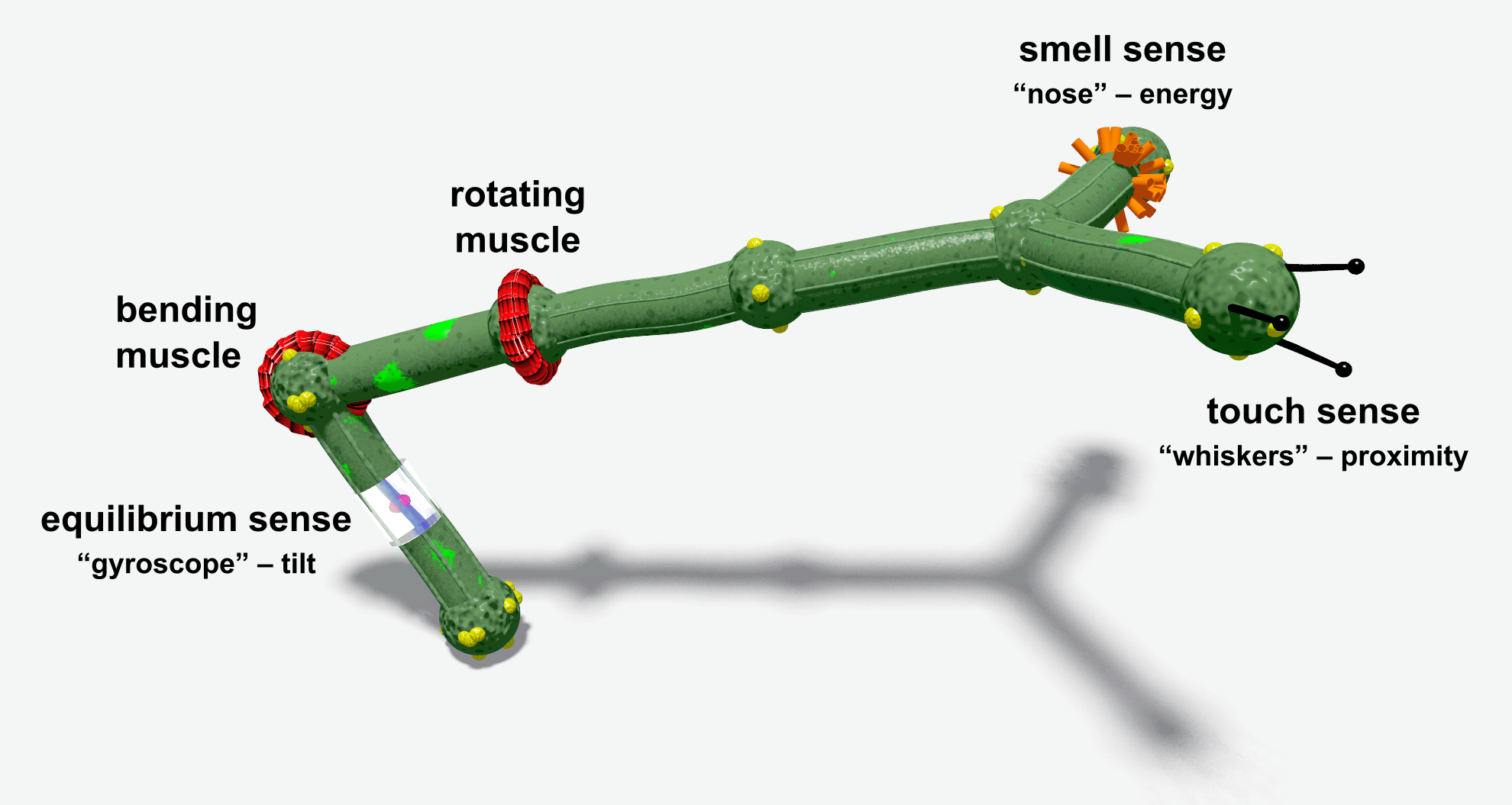
 Basic muscles (actuators) and receptors (sensors) are illustrated below.
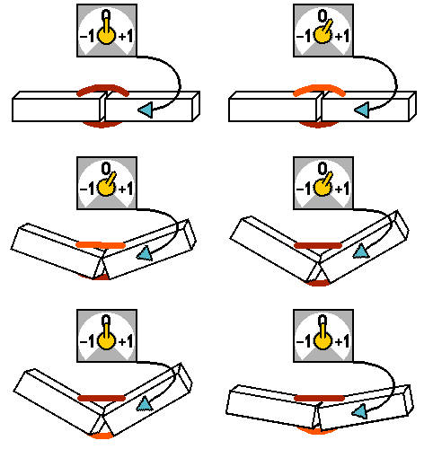
| A muscle neuron ('|' or '@' in genotype) can change the orientation of the controlled stick relative to the previous stick. This simple 2-stick creature with a bending muscle in the middle is described by the genotype "XX[|...]". The joint stays straight when the signal is equal to 0. Positive and negative values bend the construction in opposite directions. [try it!] |
 |
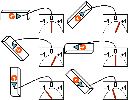 |
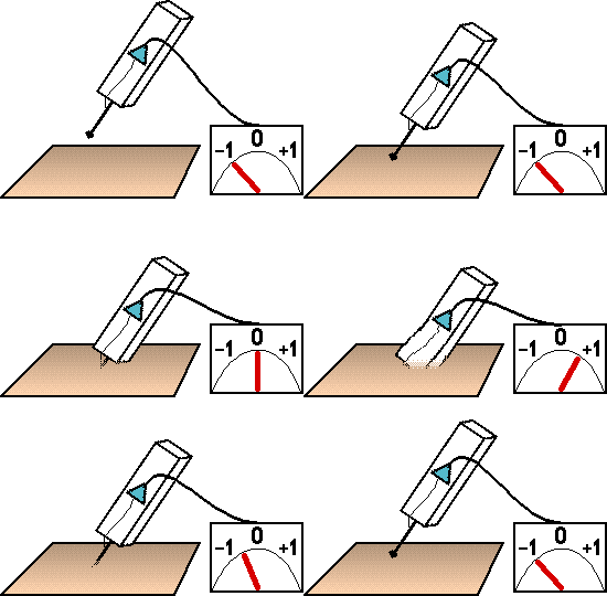
The "G" receptor (gyroscope, equilibrium sense) gives information about the stick's tilt relative to the force of gravity. A gyroscope mounted on a horizontally aligned stick outputs a 0. A vertical position is perceived as −1 or +1 depending on which end is higher. [try it!] |
 |
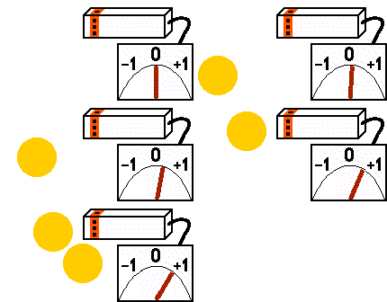
The "T" receptor (touch) can be imagined as a whisker attached to the stick. Its relaxed state is −1 (nothing detected in the whisker's range). The signal value grows as the stick gets closer to any material object. It reaches 0 when the stick touches the ground. Higher values mean that the stick is pushed into the ground. [try it!] |
 |
The "S" receptor (smell) excitation depends on the sum of the neighboring energy sources (energy balls and other creatures). The output range is from 0 (nothing detected) to 1 (maximum). Rich or closer energy sources smell 'stronger' than small or distant ones. [try it!] |
Formulas for basic effectors and receptors
| Neuron type | How simulated | ||
|---|---|---|---|
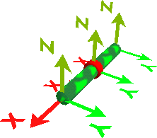
| | (bending muscle) [try enlarged] |
Changes the relative orientation of the joint's parts by rotating the second part around the first part's Z axis. Parameters:
XX[|])
//0
p:
p:1, m=2
p:2
j:0, 1, dx=1
j:1, 2, dx=1
n:j=1, d=|
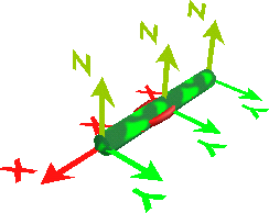
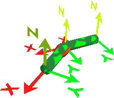
Explanation: The joint is attached to parts #1 and #2. Part #2 was rotated around the Z axis of Part #1, so its position and orientation were changed. The above pictures were created using the OpenGL visualization with the "X/Y/Z axes" option activated, which can be used to investigate Part orientations in creatures. |
||
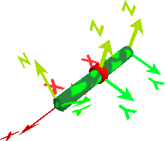
| @ (rotating muscle) |
Changes the relative orientation of the joint's parts by rotating the second part around the first part's X axis. Parameters:
Angle = Signal * 180° Sample creature (f1 genotype XX[@])
//0
p:
p:1, m=2
p:2
j:0, 1, dx=1
j:1, 2, dx=1
n:j=1, d=@
Explanation: The joint is attached to parts #1 and #2. Part #2 was rotated around the X axis of Part #1. Part #2 was not moved, because it lies on the X axis (in creatures built from f1 genotypes, all parts lie on the X axis). The above pictures were created using the OpenGL visualization with the "X/Y/Z axes" option activated, which can be used to investigate Part orientations in creatures. |
||
| G (gyroscope) [try enlarged] |
state = (part1.z – part2.z) / stick_length | ||
| T (touch) [try enlarged] |
|
||
| S (smell) [try enlarged] |
state = (sum_all_energy_sources[ energy / distance2 ])/100 (if distance<1, then use 1) |
||
| Water (water detector / water pressure indicator) [try enlarged] |
|
||
| Energy (energy level) [try enlarged] |
|
Technical muscles specification
Both muscle types (@ and |) work by modifying the relative orientation of a Part.
Relative Part orientation is expressed by 3 angles (for X,Y,Z axes), known as (rx,ry,rz) in the f0 genotype format.
The neutral position of the muscle (for the controlling signal of zero) preserves the original orientation. Other values simply add to or subtract from the original orientation, depending on the muscle type.
Joint total rotation (Tx,Ty,Tz) = joint rotation (rx,ry,rz) + muscle rotation (mx,my,mz) * Signal
- The rotating muscle (@) operates on the X axis.
Muscle rotation (mx, my, mz) = (180°, 0, 0)
which means that the muscle can do a full 360° rotation for the input signal −1..+1 - The bending muscle (|) operates on the Z axis.
Muscle rotation (mx, my, mz) = (0, 0, 180°*Range)
"Range" is the muscle attribute (called "r" in f0); the default value of 1.0 allows for 360° rotation.
The f1 converter can create limited range muscles in branches so that the movement areas of neighboring branches do not overlap.
One difference you may have noticed in the | and @ pictures is that "Bending" affected the relative location of the Parts, while "Rotating" only affected the orientation. Again, this is not a fundamental difference. This is only because of the additional assumption that Joint's (dx,dy,dz)=(1,0,0), which is always true in f1, but not necessarily in f0.
In the general case, the location of P2 is calculated in the local P1 coordinates as follows: rotate the Joint vector (dx,dy,dz) according to (Tx,Ty,Tz) and add it to the P1 location. See also the f0 Semantics of the Joint object.